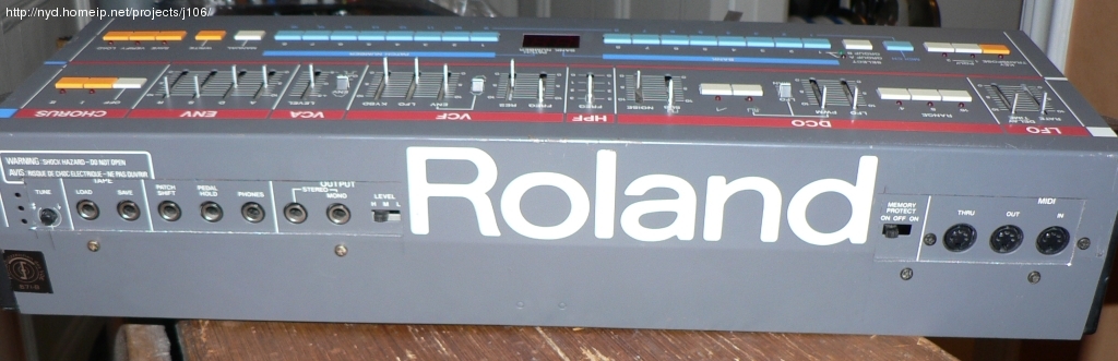
The making of the Roland Junior-106
Hole sweet hole
The original plan was to keep the MIDI board at the (seen from the back) left side, and the audio stuff at the right. Just like the original Juno. Placing them the other way around would be a better solution. Then the jack board would fit where the PSU air intake is, reaching almost to the R in the logo. The MIDI board though was simply too large to fit between the 'd'; and the side panel. The rightmost component of the MIDI board is the I/II/III switch determining the MIDI mode. A quick look at the Juno-106 schematics told me that the default mode for this parameter is III. Since that is the mode I, and almost anyone, will ever need to use I decided to cut the mode select switch from the MIDI board to save back panel space.
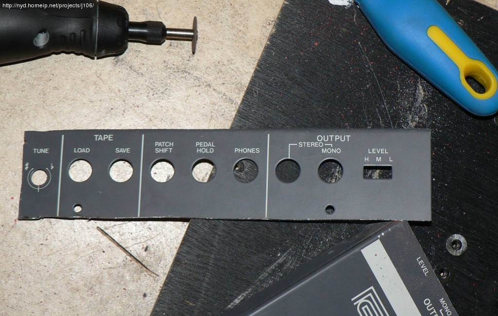
I also decided on not to drill individual holes for the seven 1/4" and three MIDI jacks, but instead to mount the original labeled jack plates on the inside of the chassis. This spared me the hazzle of aligning all holes with sub millimeter precision lettimg me instead just cut two rectangular holes large enough to show the labels and allow access to the jacks.
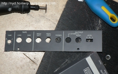
The jack plate cut out. Kept the original screw holes on the plate.
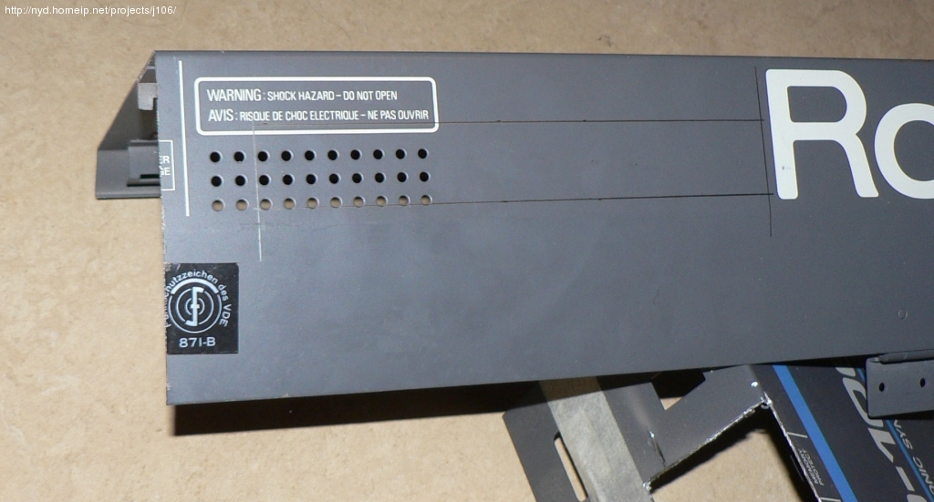
Marks for where to apply some Dremel cutting.
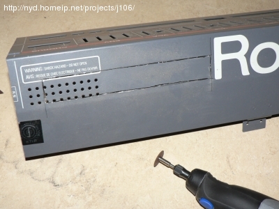
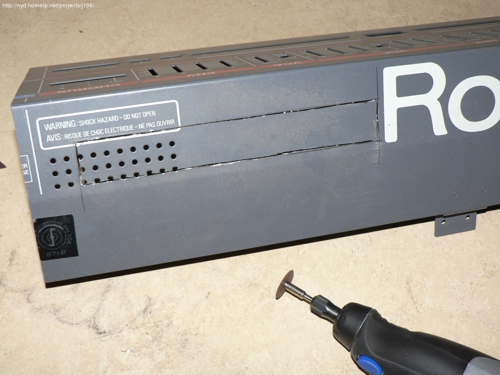
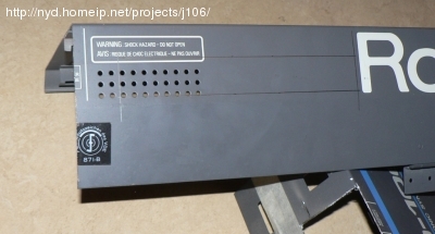
The hole has been cut, just a matter of punching it out
Here I had to spend a couple of minutes filing to get the edges smooth and straight
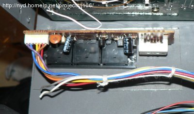
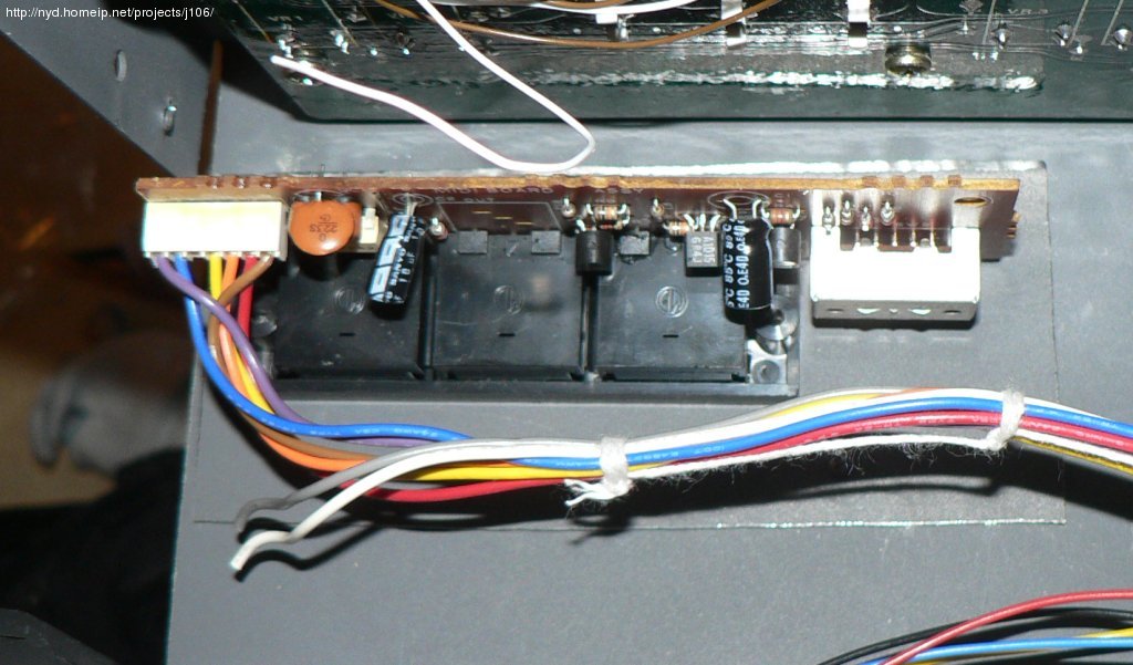
Close up on the MIDI board. The left side of the PCB, with the
MIDI mode selector, has been cut off, together with the two leftmost pins
of the white PCB-wire connector. The dangling gray and white cables
used to tell the CPU selected MIDI mode. Unconnected = mode III
Jack and MIDI boards mounted!
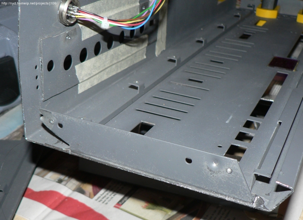
Now comes the trickiest step of making a Junior-106 - creating something for the upper side panel screws to go into. One could use some kind of steel or alu 90 degree profile for this, but I took the original mounts off the two end panels.
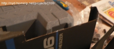
The right hand side end part with the original mounting angle for
the side panel cut off
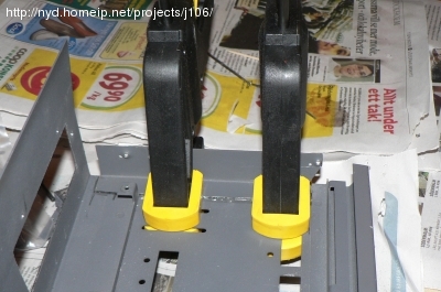
Again the epoxy adhesive came in handy. After filing off the gray
coating from the pieces to be joined I applied 24hrs of pressure
to make the glue stick rreal hard.

Since the cut off angles were placed inside the chassis, the
original holes for the side panel screws could not be used.
New ones needed to be made with very high presicion and then
threaded into M3 with a thread cutter
In this picture you can also see the mounted power intake.
Next: Internal affairs