The making of the Roland Junior-106
Transpose me
Update June 15 2009, Kerry Bradley has posted a simplified schematic (with a switch to control the octave transposing instead of piggy-backing on the front panel transpose button) you can find it on this link Kerry Bradley's Junior-106 transpose schematic
The logic behind transposing the keyboard down two octaves is simple. After cutting my keyboard at F3, the lower 3 pins of the 8-wire keyboard-CPU cable became unused, there were simply no keys connected to those pins anymore. By creating a circuit that could multiplex the remaining five signals either to pins 1-5, or to pins 4-8 I could transpose the keyboard minus 2 octaves. Since I didn't want to cut any new holes in the front panel for controlling this transpose circuit I decided to piggy-back on the signals from the TRANSPOSE and POLY-1 keys. By OR:ing the signals from those keys together with the their matrix scan line I would get a pulse if, and only if, both the TRANSPOSE and POLY-1 keys were pressed simoultainesly. I measured the panel keys scanning rate which showed that the scan line comes 610 times per second, consisting of a 13 us earthing pulse.
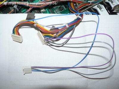
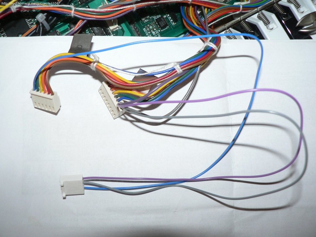
From the Panel-to-CPUboard connectors, I piggybacked on the
scan line (blue wire) and the key readout lines for the TRANSPOSE
and POLY-1 keys (pink and gray wires)
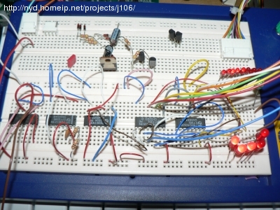
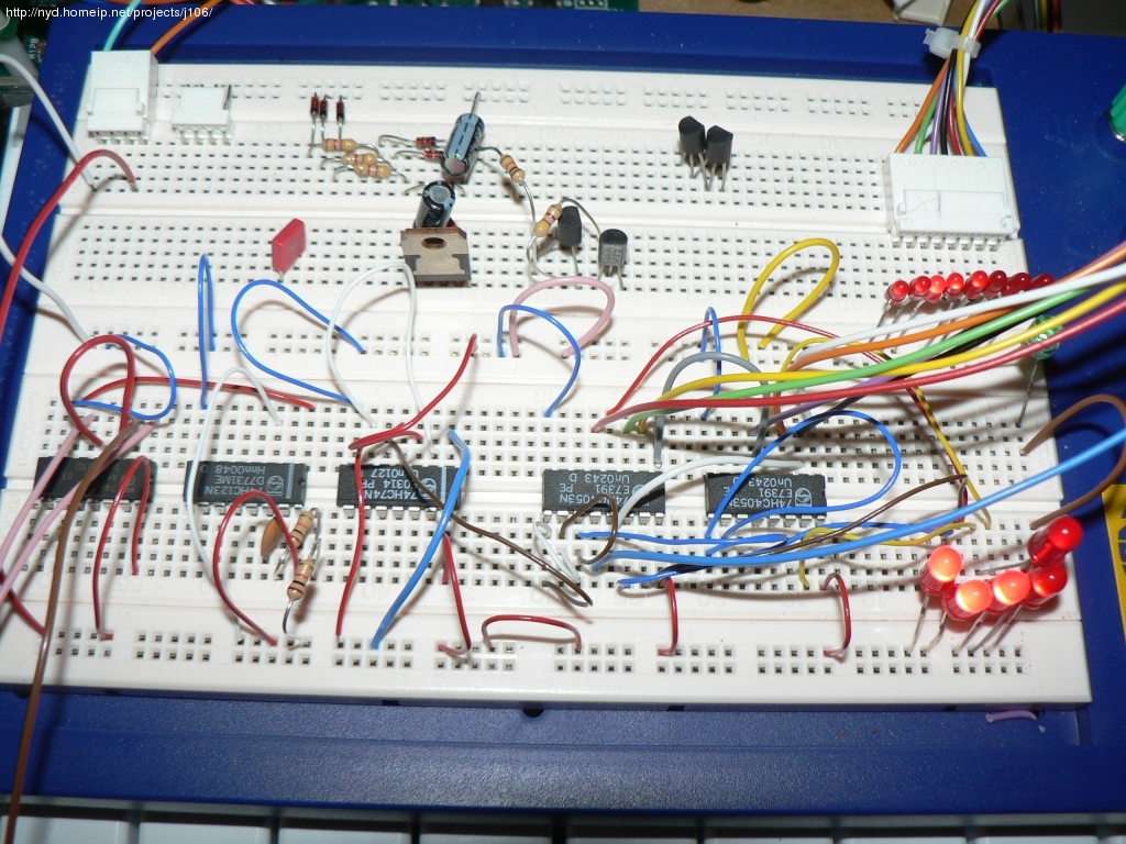
My transposer built on an experiment board. The five 5mm LED:s symbolize the 5 wires coming from the keyboard, the eight 3mm LEDS symbolize which of the eight CPU input pins those 5 keyboard lines are currently switched to.
The circuitry works like this
- The three signals from the scan line and the two keys are OR:ed
- From the OR circuit comes a 610hz signal with 13us earth pulses when both TRANSPOSE and POLY-1 are pressed
- This signal is put though a monostable multivibrator with a latch-time of sligthly more than 1/610 s
- From the multivibrator comes a clean logical one when it receives the 610hz signal
- This signal is fed to a D-latch, connected for toggling, meaning that it toggles it's exit value between 0 and 1 when an input pulse arrives
- This signal is fed to two 3-pole analog switch circuits, switching the 5 keyboard lines onto either CPU inputs 1-5, or 4-8
- The sixth, unused switch, I connected to a green LED that I placed under the TRANSPOSE key on the front panel. If the LED is lit, then the keyboard is in bass mode (F1-C4), if not lit it's in default mode (F3-C6)
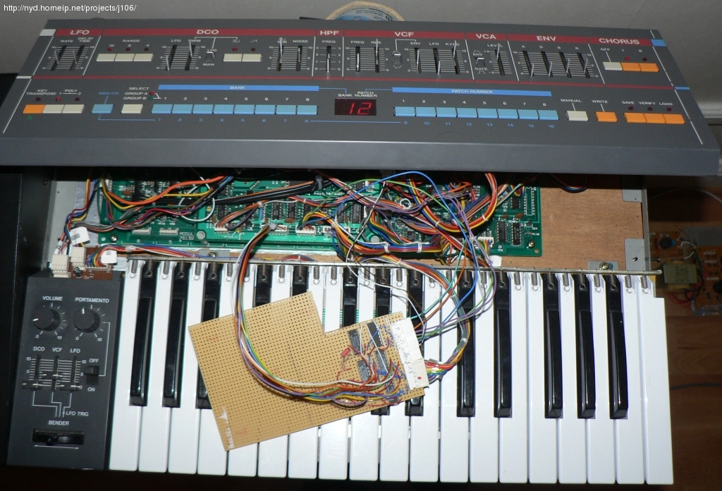
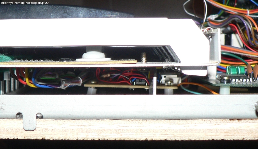
The transpose circuit. Now soldered to a "real" PCB
for in-unit testing

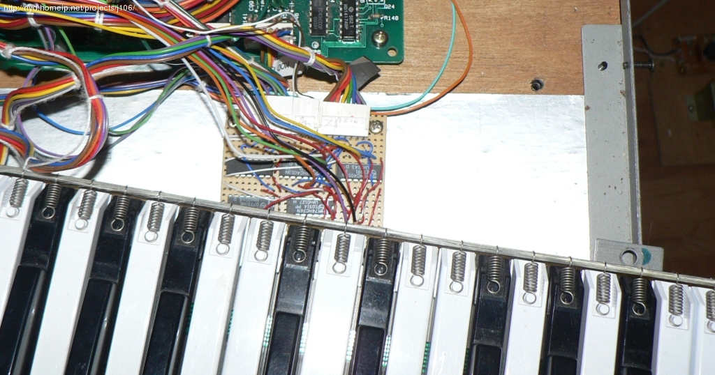
The transpose circuit cut down, and mounted onto the wooden
base board, below the keyboard. There is actually quite a lot
of space under the keyboard for future enhancements :-)
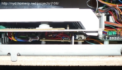
When mounted with 3.5mm plastic spacers there is about 5mm of headroom
Next: Play Me!