The making of the Roland Junior-106
The Disassembly
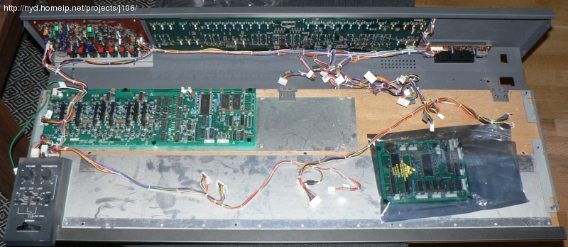
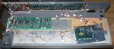
The Juno-106 is quite spacious inside and at a first look I could with 99 percent certainty say that I would be able to fit everything except the PSU inside it after cutting it down to half the size. A good thing to do is to mark up all the internal cables before removing them from the CPU/MODULE/JACK/BENDER boards.
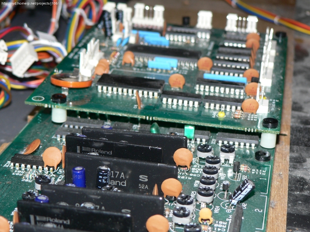
Opened up, stripped from PSU and keyboard, the CPU board is in
the anti-static bag. Click image for larger picture
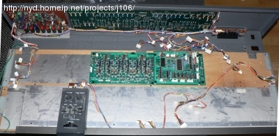
Unfastened the bender and module board, moving things around to see
where everything should fit. CPU board placed on top of the right half of
the module board.
At this point I am still planning on cutting the front panel at the two vertical white lines immediately to the left and right of the panel board. Measuring with the keyboard I realized that cutting there would allow for only a 30-note keyboard, with a G as lowest key since I want to use the top half of the original keyboard. The G-key is normally notched on both sides to accomodate a black key on each side. This would look very ugly when used as the lowest key. I could possibly order a G-key with a straight left side from somewhere, but cutting the keyboard below the F seamed easier, and gives a more usable F-C keyboard layout. The drawback is that the front panel will be 3cm wider, making it include some of the white and blue thick lines that continue to the far left and right of the unit.
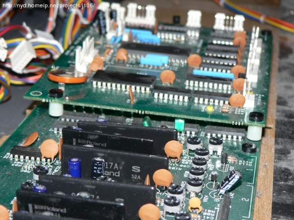
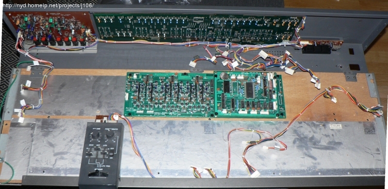
Checking how much clearance is needed for placing the CPU board
on top of the Module board. 16mm is enough, I went for 20mm
Keyboard assembly turned upside down. The cables to the CPU board
are connected at the far left side of the keyboard.
Next: Hacksaw action